In 2015, we have developped our first heat exchanger using additive manufacturing. The goal of this HX was to show that it is possible to add a thermal function inside a mechanical components, for example inside a support plate. We, thus, imagined a component similar to a plate and fin heat exchanger but limited in thickness. This HX is composed of 3 channels of 2mm heigh separated by a wall of 1mm. The central channel is dedicated to the hot fluid and the external channel to the cold fluid. We add an other constraints : each fluid must arriving and living the device on the same side. The fluid used in this case is water.
The HX was simulated on StarCCM+ CFD software, Printed in aluminium AlSi7 by Poly-Shape and tested by our Ph.D Student at IUSTI Laboratory (CNRS UMR 7343).
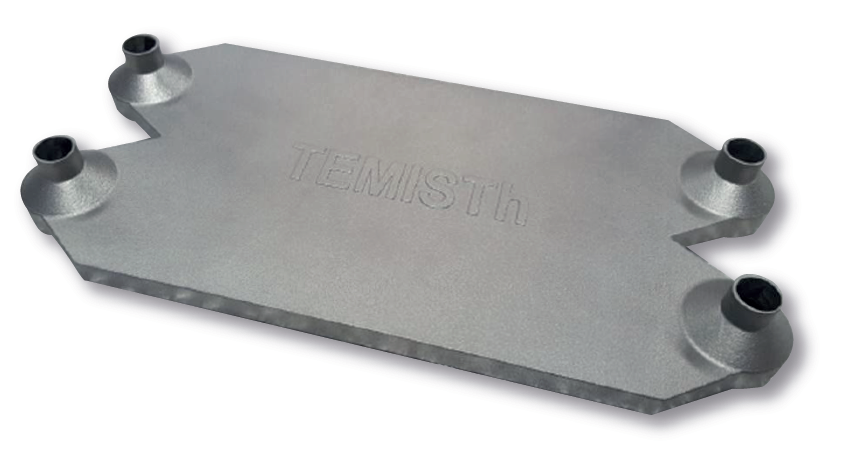
AlSi7 printed heat exchanger
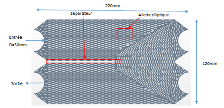
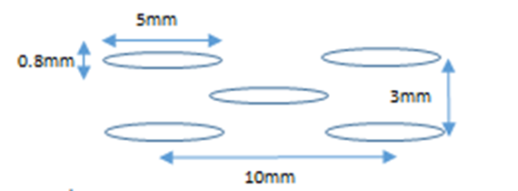
The fluid flow is following a U-shape such as shown on the figure below. Each channel is composed of fins with an elliptical shape in order to maximise the ratio between heat transfer and pressure drop. in the curve, the fins are positionned in order to adapt the fluid flow to the curvature.
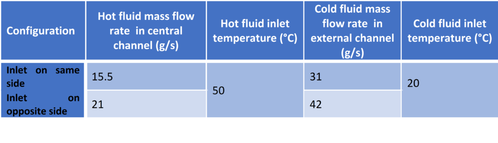
Two configurations were studied :
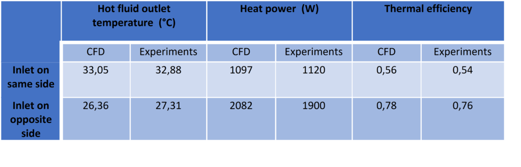
- Config.1 : Hot fluid inlet is on rigth top and cold fluid inlet on left top: Same side configuration
- Config. 2 : Hot fluid inlet is on rigth top and Cold fluid inlet on left bottom: opposite side configuration
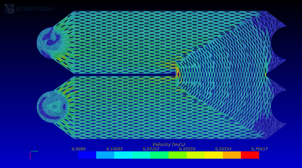
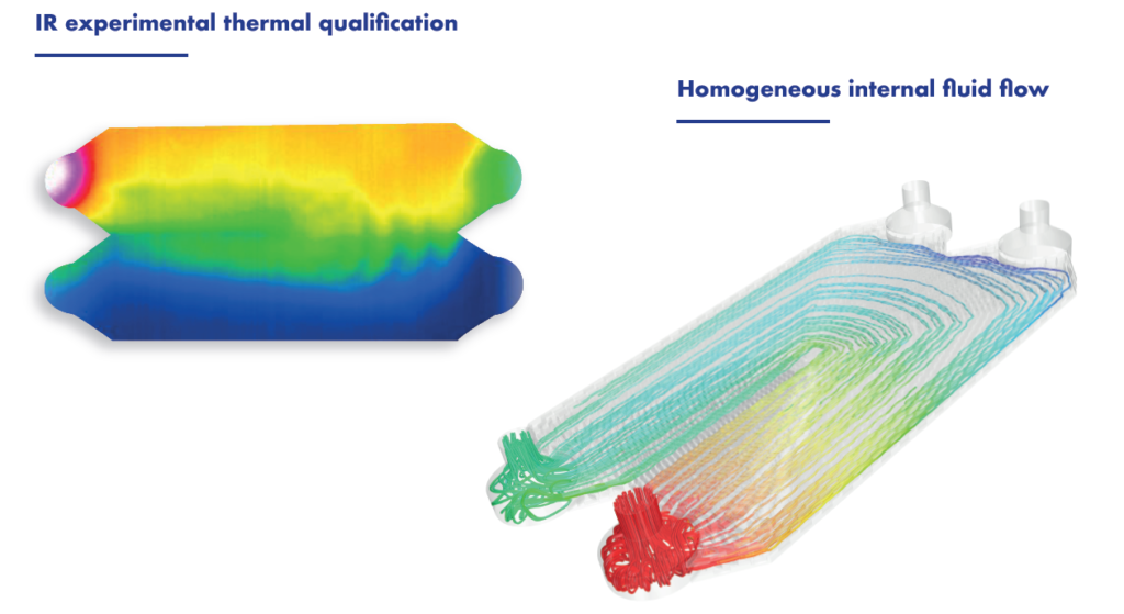
Numerical simulations were performed in order to predict thermal efficiency and analyse the performances. A good repartition of fluid flow can be observed.
The printed heat exchanger was then tested on the experimental test loops carried out by our Ph.D Student, Cédric Septet, at IUSTI laboratory in Marseille. Using IR camera he was able to ensure that the predicted homogeneous flow inside the heat exchanger are confirmed.
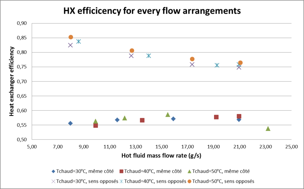
The following pictures show experimental results. The first one shows thermal efficiency for several mass flow rates and inlet temperatures for the two configurations. We observed that the opposite side configuration proposed higher efficiencies. It is due the local temperature difference that are higher in this configuration. In the same side configuration, the temperature difference betwwen fluid remain to zero, and can be inversed due to the U-shape. The second picture shows the pressure drop versus the mass flow rate flowing in the central channel (for the hot fluid).
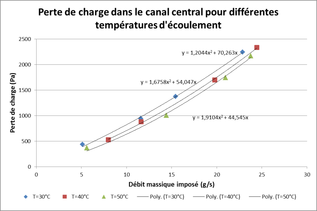
Finally, we compared the experiments to the numerical simulation : we obtained a good agreement for thermal efficiencies. However, pressure drops were widely underestimated on numerical simulation. We supposed that it is due to the surface roughness of the printed aluminium channel. No roughness model was used in the simulation.
The heat exchanger was also tested with 2 phases flows. The experimental set-up was made for both boiling and condensation configuration. The picture shows IR measurements on the HX surface. IR allows estimating over heated area and condensation area.